CIT 581 SDR Project Update 4 – April 10, 2020
Owing to the serious situation right now due to the virus, we have decided to modify our project scope. We will no longer be using any of the hardware equipment for the project. Instead, we will be simulating everything on software. Therefore, our project will now be a simulation based project whose outcome will be a simulation of the robot which we originally intended to physically build. We will be posting more detailed update on this in later blog updates.
For this blog update, we would like to share our progress up until now. We have built an initial flow of steps:
- Reading the image
- Adding the locations of the 3 Access Points
- Creating the pathway manually
- Extracting the legal points from the pathway
- Calculating fingerprints of signal strengths for each legal point
- Displaying the formed fingerprints as color gradient on the original map to show proof of concept.
The steps are better explained with pictures below:
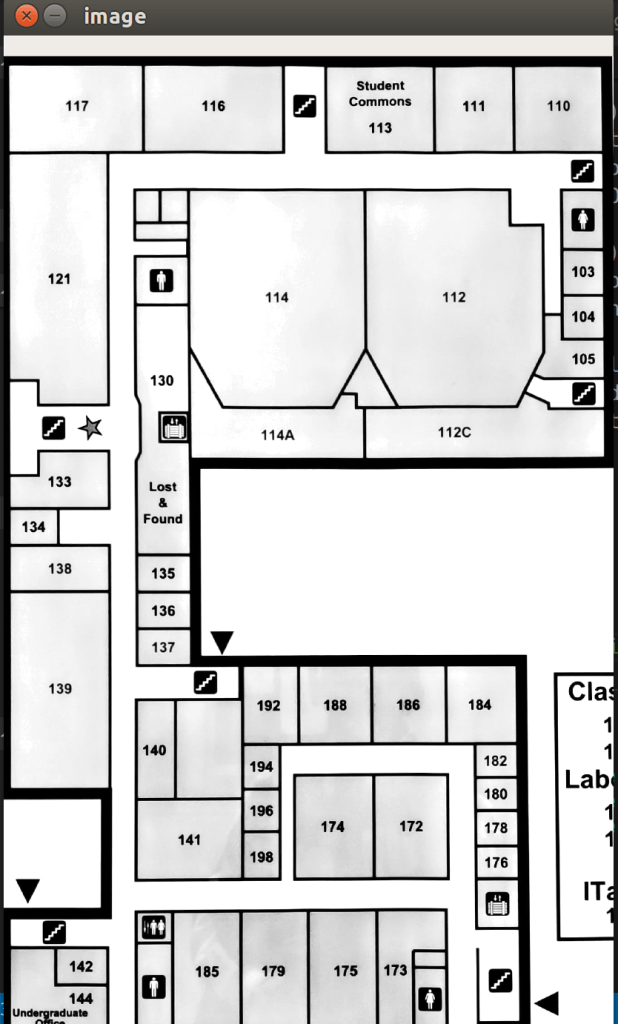
We first read the image (after converting it into a gray scale image)
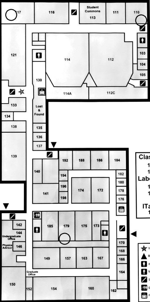
We then manually add the locations of the three Access Points in our map. The Access Points are wireless network nodes and can be used to connect to the network. Each Access Point has its own network signature. The APs have been shown below as black circles. We will make it better looking in the days to come.
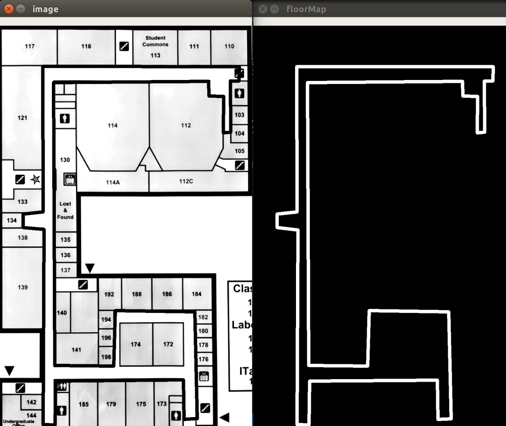
Next, we manually highlight the pathways in the floor map. In the below picture, on the left hand side map you can observe that the hallways have been highlighted in thick black lines. On the right hand side picture, you can see that our algorithm has extracted the given hall way. Note that this is just a rough proof of concept. The maps and the hallway coordinates are not accurate yet.
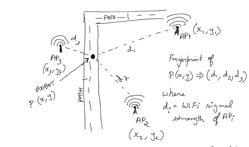
The picture below depicts how we are planning to build the fingerprints for each legal point. For each point, we record the WiFi signal strength of each Access Point. The combination of the signal strengths of each access point will be unique to a given point.
After calculating the fingerprints for each point, to prove the concept, we plot all the legal points back on the map. The color of each point will depend on the wifi signal strengths of the 3 APs. Therefore the color of each point will be a different RGB value based on its fingerprint. In the below picture, a small section of the full map has been shown. You can observe the color gradient as we move through the path way.

This has been our progress up until now. Our next immediate steps would be:
- To input the locations of offices and room numbers in the map.
- Build and develop the control system and the drive system for the robot.
We are currently considering doing the final simulation GUI in either MATLAB or Python. Since this is not an immediate priority, we will take a call on this in the days to come. Until then, we will be working on the two immediate tasks mentioned above. You can expect the next blog update to share progress on these two tasks.
Thank you!
